Part B
Identifying Geologic Structures
Geologic structures (like folds, faults, and fractures) are features that represent some type of disturbance or deformational event that affected the rock layers. Although faults can form in many tectonic settings, folds tend to form where tectonic plates collide and are commonly a result of mountain-building (like the Appalachians, Himalayas, etc.).
Stress
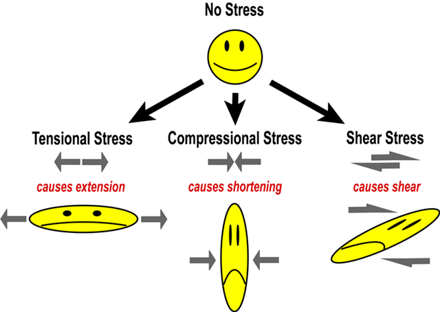
The main types of stress (a force applied over a certain area) include tension (pulling apart or lengthening), compression (squeezing or shortening), and shear (smearing or tearing in a horizontal motion). These stresses are shown in Figure 9-4. The type of applied stress uctually determines the type of geologic structure that is produced.
|
|
|
Figure 9-4. Types of stress and strain. Stress causes strain, like folding and faulting. |
Folds
Folds form in rock layers as they are slowly squeezed by compressional stresses. These stresses are a result of mountain-building processes that typically occur where tectonic plates collide (like in the Alps, Himalaya and Appalachians, etc.). As shown in Figure 9-5, folds are seen easily in a geologic cross section (side view), but they also can be identified on a map view (top view) of the Earth's surface, as represented by a geologic map. Geologic block diagrams combine these views into one model (see Fig. 9-6).
|
|
|
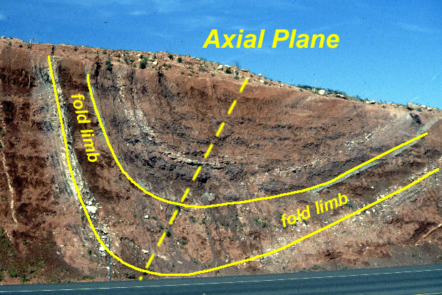
Figure 9-5. A syncline exposed in a roadcut in St. George Utah, which represents a "real life" geologic cross section. Click on the image to see an annotated version. |
Block Diagrams
We can identify different folds based on their shapes, rock ages, etc. that are commonly illustrated in block diagrams like in Figure 9-6. These model incorporate both a map view and cross section views to illustrate the geologic structures.
|
|
|
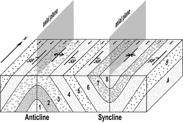
Figure 9-6. A block diagram of anticline and syncline folds. The numbers represent the relative ages of the map units (lower numbers are older). The pattern fill represents the composition of the map units. Strike and dip symbols represent the orientation of the map units. Structure symbols label the axial trace and fold type. |

Geologic Cross Section View
> In cross section, folds can be easily identified based on their shape. It's almost like having the answer key! Road cuts, stream canyon, etc. represent real geologic cross sections.
> Each fold consists of limbs (sides) divided by an axial plane (an imaginary plane that divides the fold in half at the point of maximum curvature). Axial plane orientations can range from vertical to steeply dipping (laying down).
> The type of fold is determined by the direction (toward or away from) the limbs are dipping relative to the axial plane and the orientation of the axial plane.
Geologic Map View
> Geologic map views represent the situation we typically have when there are limited vertical exposures. Still, we can use certain clues to identify and describe fold structures.
> The axial trace follows the trend of the center of the fold, and may include a geologic structure symbol that labels the type of fold.
> Look for repeating layers on either side of the axial trace. The center of the fold is the middle of a repeating sequence of layers.
> Look at the relative ages of the layers to help determine the type of fold.
> Look at the dip of the layers to help determine the type of fold.
> Sometimes curving outcrop patterns are created by plunging folds, where the fold itself is tilted.
Anticlines & Synclines
Anticlines and synclines are the most basic of fold types. Each has a distinctive shape in cross section, however, they typically look similar in geologic map view (see Figure 9-7). We need more information (like unit strike and dip, rock composition, and age) to discriminate between anticlines and synclines in geologic map view.
|
|
|
Figure 9-7. Anticline and syncline folds. |
In geologic cross section view:
> Anticline fold limbs dip AWAY from the axial plane.
> An anticline points UPWARD and forms the shape of an "A".
In geologic map view:
> As represented by the strike and dip symbols, anticline layers dip AWAY from the center (axial trace).
> The OLDEST rock unit is in the center of an anticline, and the layers are progressively younger on either side of center (young-old-young).
> An anticline structure symbol may be located along the center of the fold and has two arrows pointing away from the axial trace.
|
|
|
Figure 9-8. A block diagram of an anticline. The numbers represent the relative ages of the map units (lower numbers are older). Strike and dip symbols represent the orientation of the map units. A structure symbol is shown along the axial trace. Notice how non-plunging folds like this one have straight, symmetrical outcrop patterns. |

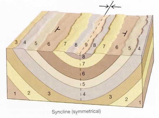
Synclines
In geologic cross section view:
> The fold limbs dip TOWARD the axial plane.
> The fold points DOWNWARD and forms the shape of an "U" or a "V".
In geologic map view:
> As represented by the strike and dip symbols, the layers dip TOWARD the center (axial trace).
> The YOUNGEST rock unit is in the center of a syncline, and the layers are progressively older on either side of center (old-young-old).
> A syncline structure symbol may be located along the center of the fold and has two arrows pointing toward the axial trace.
|
|
|
Figure 9-9. A block diagram of a syncline. The numbers represent the relative ages of the map units (lower numbers are older). Strike and dip symbols represent the orientation of the map units. A structure symbol is shown along the axial trace. |
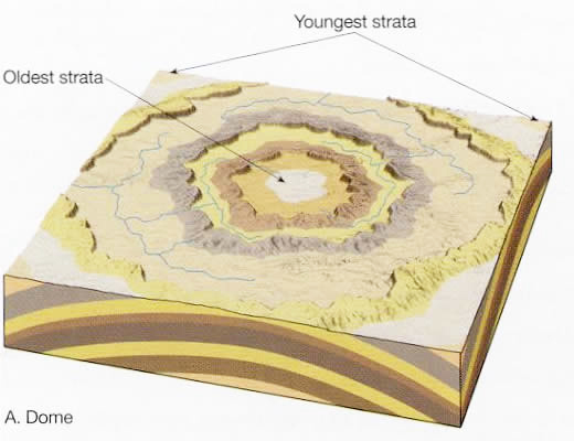
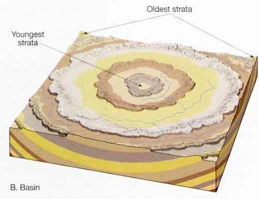
Structural Domes & Basins
Structural domes and basins are essentially circular anticlines and synclines, respectively (see Figure 9-10).
|
|
|
|
Figure 9-10. Structural dome and basin folds. |
|
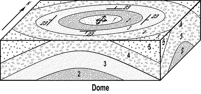
Structural Domes
In geologic cross section view:
> The layers bend/point UPWARD, forming a shape like that of a broad anticline.
> As with anticlines, the layers dip AWAY from the center of the fold.
> You can't really distinguish an anticline from a dome in cross section.
In geologic map view:
> Domes have circular ("bulls-eye"-shaped) map patterns.
> The general dip of the layers in domes resemble those of anticlines, with the layers dipping AWAY from the center in all directions.
> The OLDEST rock unit is in the center a dome, and layers are progressively younger away from the center.
> A dome structure symbol may be located in the center of the fold, and has the arrows pointing away from the center.
|
|
|
Figure 9-11. A block diagram of a structural dome. |
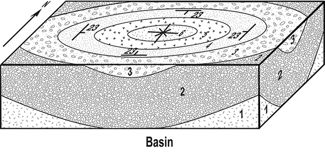
Structural Basins
In geologic cross section view:
> The layers bend/point DOWNWARD, forming a shape like that of a broad syncline.
> As with synclines, the layers dip TOWARD from the axial plane.
> You can't really distinguish a syncline from a basin in cross section.
In geologic map view:
> Basins have circular ("bulls-eye"-shaped) map patterns.
> The general dip of the layers in basins resemble those of synclines, with the layers dipping TOWARD the center from all directions.
> The YOUNGEST rock unit is in the center of a basin, and layers are progressively older away from the center.
> A basin structure symbol may be located in the center of the fold, and has the arrows pointing toward the center.
|
|
|
Figure 9-12. A block diagram of a structural basin. |
Faults
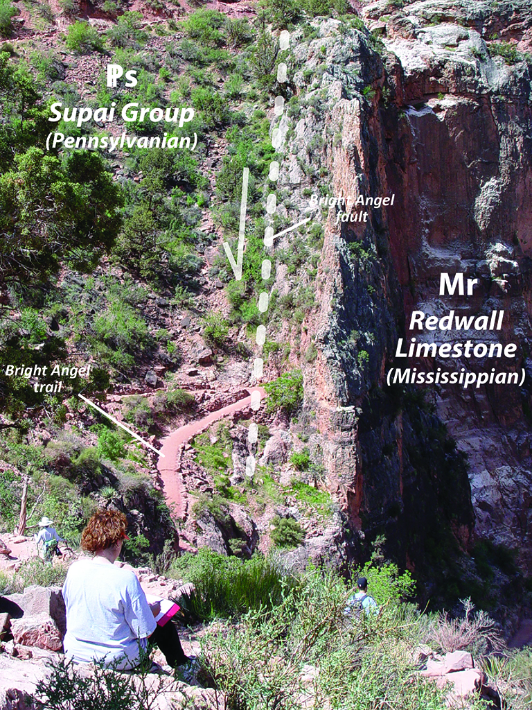
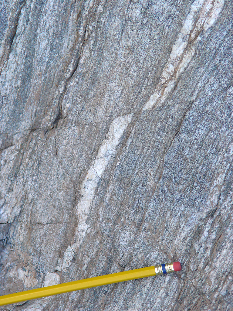
Faults are formed as various kinds of tectonic stress cause brittle crustal rocks to fracture and move. Some faults involve large amounts of offset (hundreds of kilometers), like the San Andreas transform fault, whereas others can be microscopic in scale (see Figure 9-13). The main types of stress (a force applied over a certain area) include tension (pulling apart or lengthening), compression (squeezing or shortening), and shear (smearing or tearing in a horizontal motion). The type of applied stress determines the type of fault that is produced, with each type of stress forming a different type of fault.
|
|
|
|
Figure 9-13. Faults come in all sizes. Donna sketches the offset along the Bright Angel Fault in the Grand Canyon (left). A tiny fault in the Estrella Gneiss at South Mountain in Phoenix (right). |
|
Faults are classified based on the orientation of the fault plane and the direction offset along the fault. There are two main types of faults, depending on whether movement along the fault is vertical (a dip-slip fault) or horizontal (a strike-slip fault). In many instances, two types of stress (like compression and shear) can combine to form an oblique-slip fault, which has some amount of both vertical and horizontal motion.
Dip-slip Faults
Dip-slip faults (see Figure 9-14) have two parts: a hanging wall above the fault plane, and a foot wall below the fault plane. The relative movement of the hanging wall with respect to the footwall is used to determine whether the dip-slip fault is normal or reverse. This is easiest to see in a geologic cross section.
|
|
|
Figure 9-14. A block diagram of a dip-slip fault. |
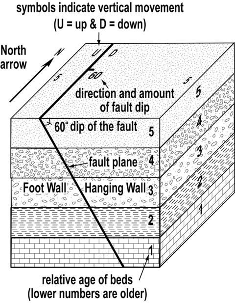
To identify a whether a dip-slip fault is normal or reverse:
> Determine which side of the fault is the hanging wall.
> Find which way (up or down) the hanging wall moved relative to the footwall. An arrow may be included to show the direction of movement of the hanging wall.
> Use the definition to name the dip-slip fault (i.e., hanging wall up = reverse fault, hanging wall down = normal fault).
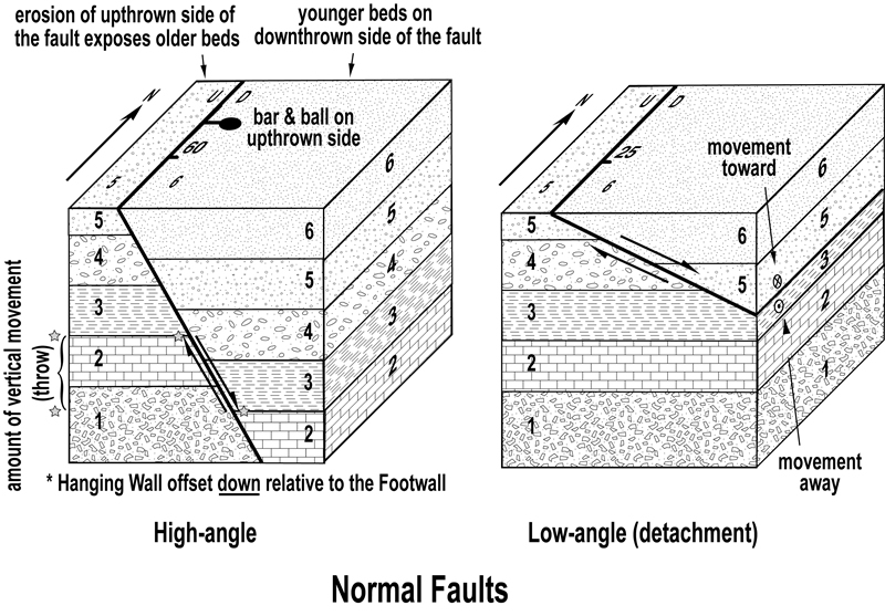
Normal Faults
> A dip-slip fault where the hanging wall block moves down relative to the footwall block (see Figure 9-15).
> Low-angle (<30 degree dip) normal faults are also called detachment faults.
> Normal faults are caused by tensional stresses.
|
|
|
Figure 9-15. Block diagrams of normal faults. |
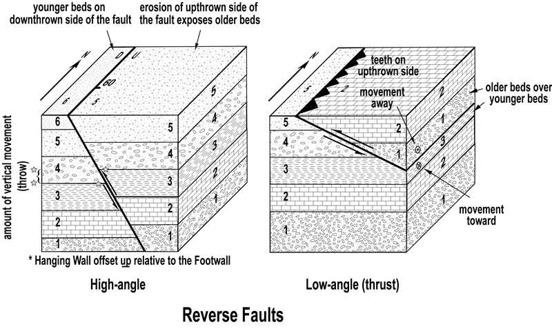
Reverse Faults
> A dip-slip fault where the hanging wall block moves up relative to the footwall block (see Figure 9-16).
> Low-angle (<30 degree dip) reverse faults are also called thrust faults.
> Reverse faults are caused by compressional stresses.
|
|
|
Figure 9-16. Block diagrams of reverse faults. |
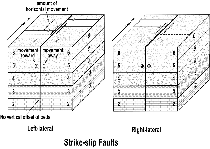
Strike-slip faults
Strike-slip faults are nearly vertical faults (no hanging wall or foot wall) that have mainly horizontal motion (see Figure 9-17). Strike-slip faults are caused by shear stresses and are defined by the direction of horizontal offset between opposing sides of the faults. Large strike-slip faults that occur at tectonic plate boundaries are referred to as transform faults.
Right-lateral strike-slip fault
> The opposite side of the fault is offset to the right.
Left-lateral strike-slip fault
> The opposite side of the fault is offset to the left.
|
|
|
Figure 9-17. Block diagrams of strike-slip faults. |