Two different examples are given below. The first is explained in detail. The second is more concise. Both examples
involve the circuit shown in the diagram at right. Voltage values are given for every circuit element. The two
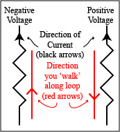
black arrows represent the directions of the current through resistors D and E. The goal of the two examples is
to determine the directions of the current through resistors A and B.
Detailed Example
Kirchoff's Loop Law states that the voltage rises and drops around any closed loop must sum to zero. A closed loop
is a path around the circuit that starts and stops at the same location. The circuit diagram that is shown at right
is identical to the one above except that a particular closed loop has been highlighted. The loop is colored green
except for resistor A, which is colored red. Resistor A is colored differently to remind you that you are trying
to determine the direction of the current through it.
To apply Kirchoff’s Loop Law, imagine ‘walking’ around the closed loop in one direction or the other. It doesn’t
matter whether you walk clockwise or counterclockwise around the loop. It also doesn’t matter where in the loop
you start because you will stop where you started. For the sake of this example, imagine that you start next to
the negative terminal of battery C and walk clockwise around the highlighted loop. Before returning to your
starting point you will walk past battery C, then resistor A, then resistor E. Hence, according to Kirchoff’s
Loop Law:
VC + VA + VE = 0
where VC, VA and VE represent the voltages across C, A and E respectively. For
this equation to be true, some of these voltages must be rises (i.e., positive) and some must be drops (i.e.,
negative).
Rules for determining whether a voltage is a rise or a drop:
The voltage across any wire is zero.
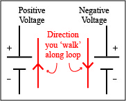
While walking around a loop, the voltage across a battery is positive if you pass by the battery from its
negative terminal to its positive terminal. The voltage across a battery is negative if you pass by the
battery from its positive terminal to its negative terminal. When walking clockwise around the green loop
in the diagram above, notice that the loop passes by battery C from its negative to its positive terminal.
Hence, VC is positive. In particular, VC = +14V.
While walking around a loop, the voltage across a resistor is positive if you pass by the resistor in the
direction that is opposite to the direction of the current. The voltage across a resistor is negative if
you pass by the resistor in the same direction as the direction of the current. When walking clockwise
around the green loop in the circuit diagram above, notice that you pass by resistor E in the same direction
as the current through resistor E. Hence, VE is negative. In particular, VE = -8V.
The diagram indicates that the magnitude of the voltage across resistor A is 6V, but since we don’t yet know
the direction of the current through resistor A, this voltage could either be +6V or -6V.
Recall that Kirchoff’s Loop Law applied to the closed loop in the circuit above resulted in the equation:
VC + VA + VE = 0
In addition, we determined that:
VC = +14V, VA = ±6V and VE = -8V.
Hence:
+14V + ±6V + -8V = 0.
This can only be true if VA = -6V.
Notice that the value of VA must be negative. This implies the direction of the current through
resistor A is the same as the direction you walked along the loop as you passed by resistor A. Since you
walked clockwise around the loop, you passed by resistor A while walking downward. That means the direction
of the current through resistor A is also downward.
Concise Example
The circuit at right is identical to the circuit in the previous example, but this time a different closed loop
is highlighted. As before, most of the loop is colored green except for one red resistor. The red resistor
is colored differently to remind you that you are trying to determine the direction of the current through it.
Imagine ‘walking’ around the highlighted loop. You can choose any starting point on the loop that you like.
You can also choose whether to travel clockwise or counterclockwise around the loop. Suppose that you start
near the negative terminal of battery C and walk clockwise around the loop until you return to your starting
point.
The order of the circuit elements around the closed loop is battery C, then battery B, then resistor D, then
resistor E.
Kirchoff’s Loop Law states that the sum of the voltage rises and drops around any closed loop is zero. For the
highlighted loop, Kirchoff’s Loop Law gives:
VC + VB + VD + VE = 0.
While walking clockwise around the green loop, you passed by battery C from its negative terminal to its
positive terminal. Hence, VC is positive.
In particular VC = +14V.
While walking clockwise around the green loop, you passed by resistor D in the same direction as the current
through that resistor. Hence VD is negative. In particular, VD = -10V.
The voltage across resistor E is negative for the same reason. In particular, VE = -8V.
The diagram shows that the magnitude of the voltage across B is 4V. Since we don’t know the direction of the
current through B, this voltage is either +4V or -4V, i.e., VB = ±4V.
Putting Kirchoff’s Loop Law together with the values we just determined for VC, VB,
VD and VE gives:
+14V + ±4V + -10V + -8V = 0.
This is only true when VB is positive, i.e., when VB = +4V.
A positive value for VB indicates that the direction of the current through resistor B is the
opposite of the direction you walked as you passed by resistor B. Since you walked clockwise around the
loop, you were walking downward when you passed by resistor B. Hence, the current through resistor B is
directed upward.