Detailed Example
Kirchoff's Loop Law states that the voltage rises and drops around any closed loop must sum to zero. A closed loop is a path around the circuit that starts and stops at the same location. The circuit diagram that is shown at right is identical to the one above except that a particular closed loop has been highlighted. The loop is colored green except for resistor D, which is colored red. Resistor D is colored differently to remind you that you are trying to determine the direction of the current though it.
To apply Kirchoff’s Loop Law, imagine ‘walking’ around the closed loop in one direction or the other. It doesn’t matter whether you walk clockwise or counterclockwise around the loop. It also doesn’t matter where in the loop you start because you will stop where you started. For the sake of this example, imagine that you start on the right side of resistor D and walk clockwise around the highlighted loop. Before returning to your starting point you will walk past resistor D, then resistor A, then battery B. Hence, according to Kirchoff’s Loop Law:
VD + VA + VB = 0
where VD, VA and VB represent the voltages across D, A and B respectively. For this equation to be true, some of these voltages must be rises (i.e., positive) and some must be drops (i.e., negative).
Rules for determining whether a voltage is a rise or a drop:
- The voltage across any wire is zero.
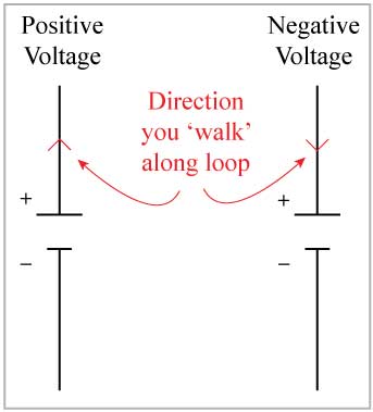
- While walking around a loop, the voltage across a battery is positive if you pass by the battery from its negative terminal to its positive terminal. The voltage across a battery is negative if you pass by the battery from its positive terminal to its negative terminal. When walking clockwise around the green loop in the diagram above, notice that the loop passes by battery B from its negative to its positive terminal. Hence, VB is positive.

- While walking around a loop, the voltage across a resistor is positive if you pass by the resistor in the direction that is opposite to the direction of the current. The voltage across a resistor is negative if you pass by the resistor in the same direction as the direction of the current. When walking clockwise around the green loop in the circuit diagram above, notice that you pass by resistor A in the direction that is opposite to the direction of the current through resistor A. Hence, VA is positive.
Notice that both VB and VA are positive. Recall that Kirchoff’s Loop Law applied to the closed loop in the circuit above resulted in the equation:
VD + VA + VB = 0.
Put into words, this says that when VD is added to two positive voltages (VA and VB), the sum is zero. Hence VD must be negative. For the voltage across resistor D to be negative, the direction of the current through resistor D must be the same as the direction that you walk while passing by resistor D. Since you are walking clockwise around the loop, the current through resistor D must be directed to the left.